
Variable Depth Slab Bridge Design Software – Technical
V Slab Technical Help Section
This section provides a comprehensive overview of the operations of the software as well as the details of implementation. Where applicable, code reference sections are included and notes are provided to assist the designer in addressing pertinent code requirements.
- Introduction
- Bridge Data
- Slab Data
- Materials
- Ld / Splice
- Default Values
- Loading Specification
- Loading Application
- Analysis
- Reinforcing Layout
- Section Checks
- Substructure
- Report Page
V Slab follows code requirements of the American Association of State Highway Transportation Officials (A.A.S.H.T.O.) LRFD Bridge Design Specifications, Customary U.S. Units, 9th Edition. Design requirements and details vary by state as well as by engineer. This software must be used under the direct supervision of an experienced design professional to ensure compliance with Federal, State and local requirements.
The sign convention used in this program assumes positive moments create tension on bottom surface and likewise negative moments create tension on top surfaces.
For the purposes of this help menu, items included in brackets [ ] are references to the applicable section of the AASHTO LRFD Specification. For references to the AASHTO Manual for Bridge Evaluation, 3rd Edition 2018 with Interim Revisions through 2019, items are included in brackets preceded by an R as [R- ].
Once the program has been installed, it will open to the start page. Enter your user name and password and select the “Approve License for Use” button. The program can be run in Demonstration Mode with limited features. To utilize all of the programs features, you must have a valid user name and key code as well as internet access.
There are two options to start using V Slab. You can Open an existing project or start a New project. Select your choice on the toolbar along the top of the window. The input parameters from previously saved projects are loaded using the Open feature. Only the input parameters are saved. The results of an analysis are not saved as this would require significant memory to store the various arrays of data. The bridge will be reanalyzed when you proceed to the reinforcing layout window using the next button.
If New project is selected, default values will be loaded for the most recently saved items. For more details about entering default values, see the help section on this topic.

After entering a job description, you can begin entering span lengths. Up to nine spans can be entered. The span lengths must be between 10 and 90 feet. If more than one span is entered, adjacent spans are continuous. If you want adjacent simple spans, you must run them as separate projects and complete the substructure design by other means.
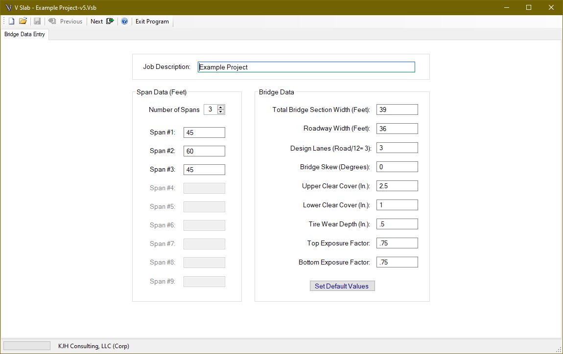
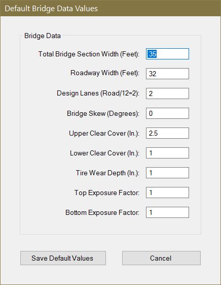
The total Bridge Section Width must be between 12 and 120 feet. The roadway width cannot exceed the total section width. The difference between the bridge width and roadway width is the railing width. The roadway width also serves as the loaded area for the future wearing surface (see load specification section).
The number of design lanes is left to the designer, but the value in [3.6.1.1.1] is presented and checked when the user leaves the page. Overriding this value affects the design of both the superstructure and substructure. Overriding the calculated value should be completed only after careful consideration of the affects.
The bridge skew must be between 0 and 45 degrees. The upper and lower clear cover must be between 0.5 and 5.0 inches. The tire wear depth must be between 0 inches and the upper clear cover depth.
The exposure factor (γe) is used in equation [Eq. 5.6.7-1] for crack control maximum reinforcing spacing. This value is described as 0.75 for Class 2 Exposure and 1.0 for Class 1 Exposure. Since the crack width limits are subject to individual owner requirements, values from 0.5 to 2.0 are allowed in the program. Different values can be provided for top and bottom steel layers to account for potentially different exposure conditions.
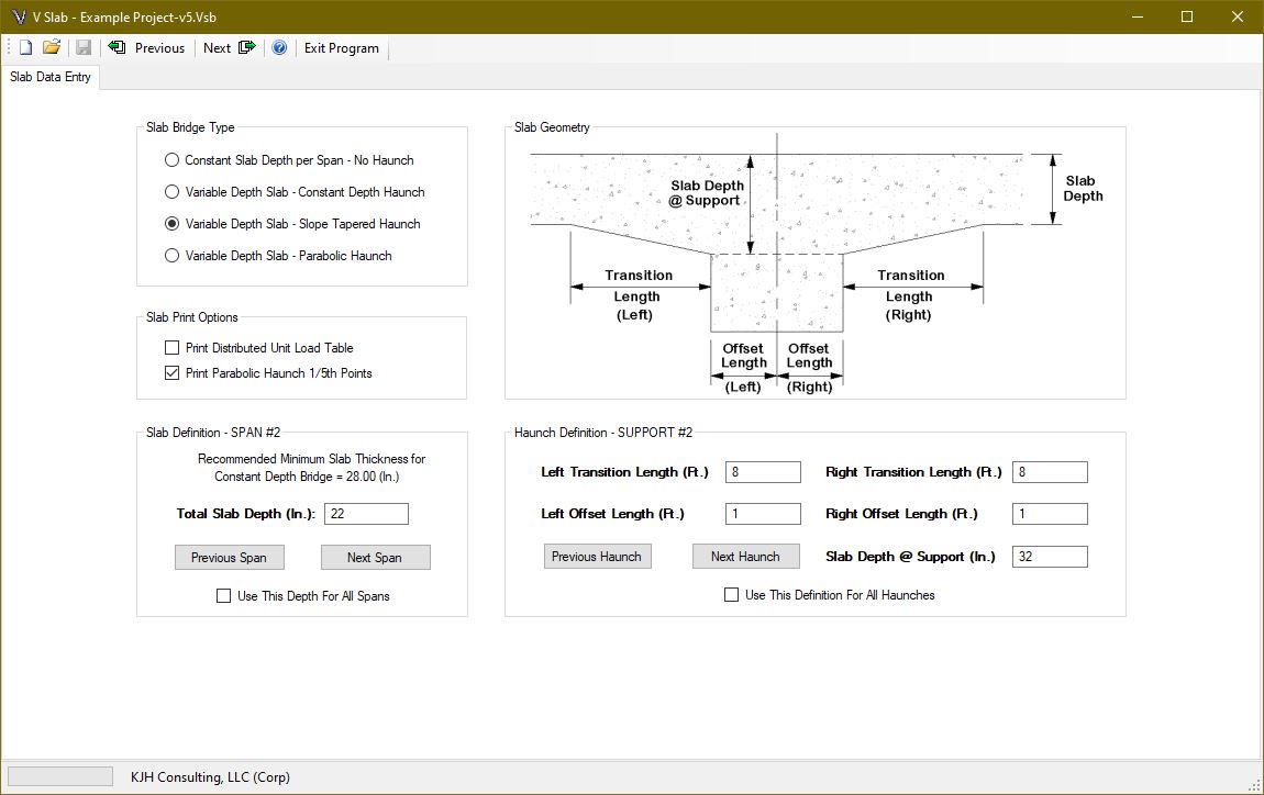
When the bridge data page is complete, click the next button to enter the slab data page. The bridge can be designed as a flat slab or one with a variable depth. Variable depth slabs have haunches at interior supports for continuous spans. Three variable depth slab options are available: Constant Depth Haunch, Slope-Tapered Haunch and Parabolic Haunch.
Variable depth slabs pull positive moments away from the span to the negative moment region over the interior supports where they can be more efficiently carried by the deeper slab thickness. The interior slab can therefore be thinner than the minimum recommended depth by AASHTO as the depth at the interior support is typically thicker than the minimum. This is not only more structurally efficient, but the dead load moments are also reduced due to the distribution of concrete thickness.
NOTE TO DESIGNER: The program assumes the main reinforcing steel is placed in a mat parallel with the top surface. For positive moment design, the effective depth will be calculated using the slab thickness for the span, and will be constant throughout that span. For negative moment design, the effective depth will change as the haunch depth varies. Supplemental reinforcing in the haunched section is not defined in the program.
There are 14 design points for each span. For a flat slab these locations are equal to the span length divided by 14. For a variable depth slab, a point will be placed at the end of the haunch and at the offset location. The distribution of the other points depends on the relative length of the span and haunch length.
The structure stiffness matrix and fixed end forces are numerically integrated using Gauss Quadrature for variable depth members. Since the slab dead load is not constant for a variable depth slab, there is an option for printing a unit load table if the designer needs it.
Depending on the haunch layout, the required maximum negative moment steel may not occur over the interior support. The designer should review the calculated required steel at each design point to ensure proper haunch configuration.
For parabolic haunches, the depths at 1/5 points can be printed to ensure proper dimensioning during slab detailing. The equation used to determine the slab depth is determined by calculating a constant “K” which is equal to ( transition length2 ) / ( slab depth @ support – slab depth @ span ) . The slab depth at a point “X” measured from the end of the transition is equal to the slab depth in the span plus ( X2 ) / K.
For example, to find the depth at 6 feet from the end of a 10ft. haunch with a 20 inch slab and 30 inch deep haunch at the support, the following is calculated:
K = ( 102 ) / ( 30 -20 ) = 10
Haunch Depth (@ 6 Ft.) = 20 + ( 62 ) / 10 = 23.6 inches
Note that the calculation is always from the span side of the transition to the offset location.
When the slab data page is complete, click the next button to enter the material data page. Enter the reinforcing steel yield strength and whether the top and bottom reinforcing bars are epoxy coated. This information is used for the cut bar development and splice length calculations.
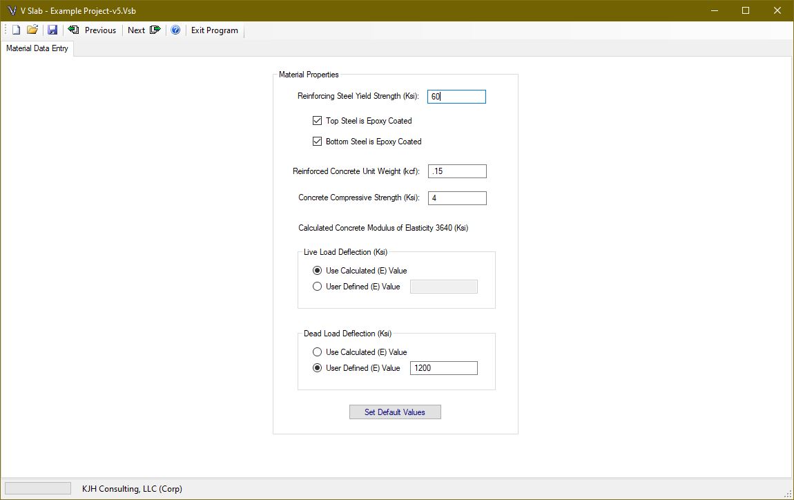
The unit weight of reinforced concrete is entered. Only normal weight concrete, as defined by the code, is used for calculation purposes. After the concrete compressive strength is entered, the calculated modulus of elasticity is displayed. This value can be overridden for live or dead load deflection calculations.
Live load deflections are optional and can be owner specific. For this program, the live load deflection calculations are the larger of a single truck or 25% of the truck with full lane loading [3.6.1.3.2]. Deflections are based on service loads (load factor of 1.0) with the dynamic load allowance of 33% applied to the truck portion only. The live load is adjusted for the number of loaded lanes, and gross cross sectional properties of the bridge are used.
The live load deflection can be adjusted to a pseudo-cracked condition by modifying the modulus to a value lower than calculated, see [5.6.3.5.2] for guidance. To account for lower initial concrete strength when the forms are removed, the dead load modulus can also be adjusted. The modulus of elasticity is prescribed in [5.4.2.4]. This equation has correction factors for lightweight concrete. Since V Slab assumes normal weight concrete, the modulus is calculated using equation [C5.4.2.4-3].
When the material data page is complete, click the next button to enter the reinforcing development and splices page. This page allows the user to select the development and splice data for the project. The values can be calculated or user defined values can be entered. For calculated values, the assumptions related to development factors are displayed.
NOTE TO DESIGNER: The program assumes top bars will have 12 or more inches of concrete below the bars (most typical bridge slabs) and the bottom bars will have less than 12 inches of concrete below the bars. For bottom bars at haunches and supports, this could be exceeded. However, the concrete cover would also increase with the depth. Most of the assumptions, related to development lengths, will produce conservative results. Any unique and/or specific conditions should be reviewed by the designer. The designer has the ability to override the reinforcing development table to provide more or less conservative values.
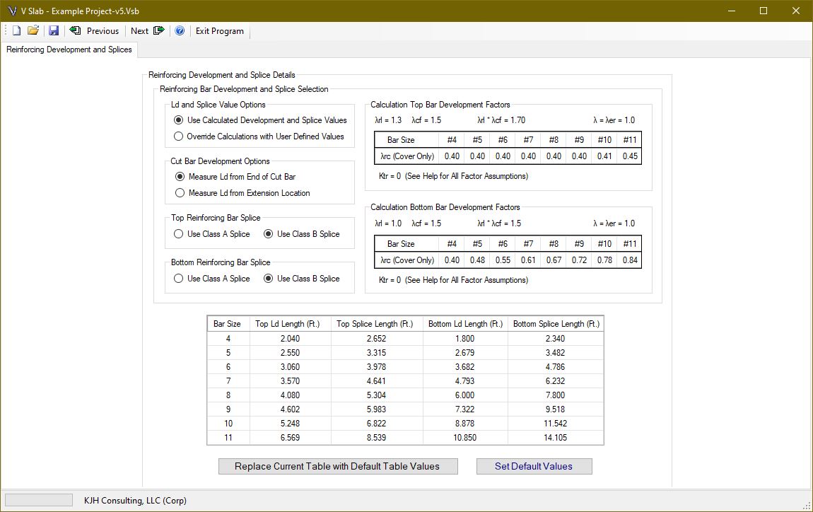
Splice types must be selected for top and bottom bars if the calculated values are used. The development and splice values in the table will be used for the project when the next button is selected. These values can be stored as default value, or retrieved, if previously saved.
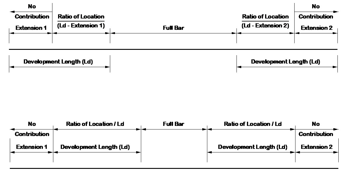
A special feature is included to address the cut bar development length location calculation. The code requires the cut bar to be extended a certain distance past the point where it is no longer needed. This is called the cut bar extension. The required extension is calculated for both ends of the bar. However, the code does not address whether this extension contributes to the development length of the cut bar.
The extension is physically a part of the bar, and designers have used it in the past. Since the current code is silent on this issue, an option is included. As such, the designer has the option of ignoring the extension portion from the development length, or including it. See Section Checks for a discussion on the area of steel calculations related to these options.
Many times there are typical values that are used for all, or most, of the bridges an engineering firm may design. This can be beneficial for projects within a specific area or state. Dimensions like clear cover, tire wear depth and general substructure configurations will likely be local standard.
Material properties for steel and concrete are also typical for routine designs. Many times general loads for railing and future wearing surface as well as load settings and applications will benefit from default settings. These settings are intended to minimize data entry for new project setup.
Some bridge data cannot benefit from default values. Items like the number of spans and span lengths are rarely typical. Likewise, slab depths and haunch configurations are directly related to span data and are therefore not provided with default data entry options either.
Where default data options are provided, a button will be available at the bottom of the entry page. The user can update the values at any time which will be saved in the programs user configuration after the program closes. These default values will then be used to populate data fields for new projects.
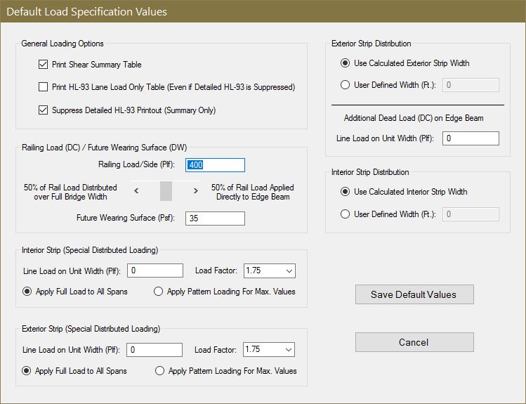
Once the general bridge data and materials are entered, the applied loading must be specified. The railing load is entered in pounds per foot (plf) and is assumed to be applied on both sides of the bridge. In other words, the total load is twice the plf load entered. This rail load is applied by adjusting the track bar. The specified percentage is distributed over the entire bridge width, and the remaining percentage is applied directly to the exterior Strip. If the bridge span is long and the width is narrow, the rail loading will tend to distribute more evenly over the width. Therefore, the distribution percentage will be higher. If the bridge span is relatively short compared to the width, the rail load will likely be more concentrated along the edge beam.
It is up to the designer to specify the appropriate percentages. Some transportation departments may require the railing load to be entirely distributed over the bridge width, while others may choose to apply the rail load entirely to the edge beam. The code does not specify a provision regarding this distribution. However, it is the author’s opinion the load will be shared based on the three dimensional effect of the span to width ratio.
The future wearing surface is provided in pounds per square foot (psf). It is applied directly to the interior strip width. For the edge beam, it is applied to the roadway portion only. (i.e. if the roadway width is less than the bridge width, the edge beam future wearing surface will be a ratio that reduces the load to account for the railing location)
Three additional loading options are provided for unique cases. A distributed line load can be applied to the interior and exterior strip. These are unit width loads and must be calculated by the user accordingly. If a live load is being modeled, the pattern loading toggle can be selected to produce the maximum force effects. Otherwise, the entire surface can be loaded using the full load toggle. A load factor between 1.0 and 1.75 at 0.05 increments can be selected. This same load factor will be used for design and load rating if the loading is applied. An additional dead load (applied with a DC load factor) can be applied to the exterior strip. This was intended to account for additional sidewalk dead load on the exterior strip.
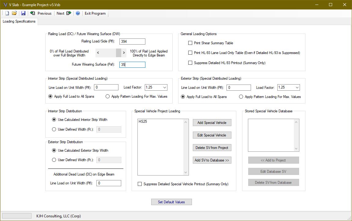
To reduce the amount of output, you can check the “Suppress Detailed HL-93 Printout (Summary Only)” box, and/or the “Suppress Detailed Special Vehicle Printout (Summary Only)” box. You can modify default values by selecting the button at the bottom of the screen. If the designer requires more detailed information about the HL-93 envelope, the “Print HL-93 Lane Load Only Table” can be selected to help determine the component parts of the envelope.
If the designer wants to see shear loading values for the superstructure, select the “Print Shear Summary Table” checkbox. A table is provided in the report with factored values for the slab only, and for the design unit width for interior and exterior strips. The strips include dead and live loading.
In addition to HL-93 loading, the program will analyze special vehicles and design for the maximum resulting load cases. Special vehicles are created at the project level using the “Add Special Vehicle” button. Once created, the vehicle can be added to the special vehicle database that is saved separately from the project file so the vehicle can be added to other projects without having to re-enter the same information. A vehicle in the database can be added to a project by highlighting it and selecting the “<<Add to Project” button. A special vehicle can be edited as needed after it is created.
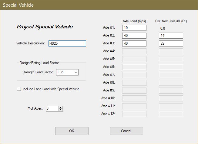
Special vehicles can be analyzed with or without the standard 640plf lane load included. In addition, the user can set the strength load factor to be used. The 33% dynamic load allowance is applied to the vehicle portion, but not the lane load if included.
After defining the loads, the next step is to determine how they are applied. Two types of vehicular loading can be applied to the structure: HL-93 and Special Vehicles. HL-93 loading [3.6.1.3] consists of a tandem, with lane loading or one variable spaced axle design truck, with lane load. In addition, for negative moments and interior support reactions, the provisions of [3.6.1.3.1] for 90% of two trucks spaced at 50 ft. apart with lane loading is checked. Lane loading is pattern applied at tenth points to achieve maximum affects. A dynamic load allowance [3.6.2] of 33% is applied to the truck and tandem (not the lane loads).
Fatigue loads are calculated in accordance with [3.6.1.4]. A dynamic load allowance [3.6.2] of 15% is applied to the fatigue truck with a load factor of 1.75 for fatigue type I and 0.8 for fatigue type II. The distribution width for a single lane is used in accordance with [4.6.2.3-1]. This width is multiplied by 1.2 in accordance with [3.6.1.1.2], specifically the commentary regarding fatigue. The fatigue load on the exterior strip is equal to the interior strip.
Special vehicles are analyzed similar to the HL-93 loading. A dynamic load allowance [3.6.2] of 33% is applied to the vehicle (not the lane load if applicable).
Two load application definitions are available. The first defines the design envelope case for creating the required reinforcing layout. The second is intended for the post-constructed and potentially deteriorated load rating case.
The code allows an adjustment (reduction) of the live loading to account for bridge skew. Since bridge skew creates a shorter span distance diagonally between the supports, the live load longitudinal superstructure moments are reduced as the skew increases. Select the checkbox, for each definition, if you want the program to reduce the live load moments according to [Eq. 4.6.2.3-3]. It is always conservative to leave this unchecked.
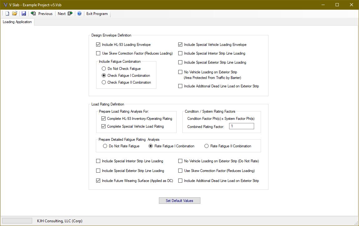
DESIGN ENVELOPE
The design envelope is a combination of loading intended to create the case for initial design and detailing. The loads are applied as specified and the required area of steel is calculated at each design point. The reinforcing layout is prepared to satisfy the design envelope case.
To model a sidewalk condition, vehicular traffic can be eliminated from the exterior strip. These combinations allow the user to design for a given condition and then load rate for a different prescribed loading/combination.
LOAD RATING
The load rating combination is intended to provide post-constructed capacity and the associated “Rating Factor” (RF). The effective condition of every bar, to simulate corrosion, can be entered on the reinforcing layout page to follow. Since it is customary to load rate only applied loads, the future wearing surface can be eliminated, or if actually measured and applied, is treated as a dead load with a load factor of 1.25 [See Notes Below R-Table 6A.4.2.2.1].
See V Slab Help Section “General” for [R-] reference sections.
Equation [R-6A.4.2.1-1] was modified to accommodate the loading conditions used in the program. This load rating equation is indicated below. The term “Special” is included to identify the portion of load related to the special line loads added to the interior or exterior strip. The load factor defined by the user on the load specification page will be used for all load ratings. The HL-93 Inventory and Operating conditions are evaluated using the load factors of 1.75 and 1.35 respectively [R-6A.4.3.2]. For special vehicle load ratings, the user defined load factor will be used for the vehicle and lane loading, if applicable.
RF = [ ∅c ∅s ∅Rn – γdc (DC) – γspecial (Special) ] / γL ( LL + IM )
The two terms ∅c and ∅s are the condition and system factors. These are described in [R-6A.4.2.3] and [R-6A.4.2.4]. The system factor for a slab bridge [R-Table 6A.4.2.4-1] is typically 1.0 and the condition factor depends on the deterioration of the bridge. The condition factor ranges from 0.85 to 1.0 depending on the SI&A Inspection Rating (See Commentary). For the purposes of the rating equation, these terms should be entered as a combined rating factor consisting of the product of the two selected values. In the event a system factor other than 1.0 is desired, multiple the two factors together and enter the resulting combined factor.
A detailed fatigue rating can be completed if desired. This is provided to check the deteriorated condition for fatigue loading and to provide reinforcing stress ranges. The effective reinforcing steel percentages are used, but the system and condition factors are not applicable, because this is a service condition check.
Once the bridge data is complete, selecting the next button will start the bridge analysis routines. The progress bar at the bottom of the command line will display the status of the analysis. The analysis is completed in the following steps:
- Create the structure model and stiffness matrix.
- Create influence values.
- Find HL-93 loading
- Find Special Vehicle loading
- Determine Interior and Exterior strip loading
- Calculate slab reinforcing requirements
- Present reinforcing layout for designer review
Programming details for load calculations are not presented for simplicity purposes. Many of the appropriate loading methodologies are presented throughout these help sections. V Slab uses an optimized banded matrix solver to complete the loading analysis of the bridge. Since there can be thousands of truck and lane load combinations to find the maximum design values at intermediate points, this method makes the calculations nearly effortless on most computers.
When using a standard flat slab option, the stiffness coefficients have fixed constants. For a variable depth slab option, the analysis routines use Gauss Quadrature to numerically integrate the stiffness coefficients as well as the member fixed-end forces. These stiffness coefficients are assembled into the structure banded stiffness matrix. The banded solver then generates the displacements, internal moments/shears and reactions for the structure.
The Reinforcing Layout section discusses the process of designing slab reinforcing, which is based on a two bar reinforcing pattern for both top and bottom steel. Shear strength calculations are not required by the code [5.12.2.1] since the moment design is in accordance with [4.6.2.3]. If the designer desires to review the shear loading for the superstructure, a shear table can be printed in the report (see Loading Help Section).
The load rating calculations are completed immediately prior to preparing the report, since the reinforcing layout must be finalized before determining the capacity of the superstructure.
When the analysis is complete, the results will be displayed graphically for designer interpretation as described in this section. The strip width is calculated in accordance with [4.6.2.3]. This can be changed to a user defined value. The maximum negative and positive area of steel are calculated using the effective depth for bar sizes #4 through #11. In accordance with [5.5.4.2 & 5.6.2.1, the reinforcing strain is checked. If the maximum strain is greater than the tension control strain, the section is tension controlled and a Phi Factor of 0.9 is used. For strains less than the compression control strain, a Phi Factor of 0.75 is used. Between these two limits, a transition Phi Factor is used.
The required area is compared to the minimum area of steel, which is equal to 1.2 times the cracking moment [5.6.3.3]. This utilizes variability factors that include reinforcing steel types. Since yield strength is the only reinforcing parameter entered, the more conservative of each factor is utilized. In addition, the modulus of rupture [5.4.2.6] includes a concrete density modification factor. V Slab assumes the use of normal weight concrete only and therefore uses a factor of 1.0 in the equation. The lesser of the minimum area or 1.33 times the calculated area of steel is provided. The fatigue stress range of the resulting area of steel is checked as specified in [5.5.3.2]. If the stress range is exceeded, the area of steel is increased until it is satisfied.
Temperature and Shrinkage steel is also calculated and provided as a minimum value. Minimum T&S steel is calculated using equation [5.10.6-1]. The slab depth at midspan is used for the least thickness, and the least width is the smaller dimension of the bridge width or the bridge length (in inches). This minimum steel is required in each face and in each direction. Additional reinforcing requirements may be necessary at haunch conditions. The design engineer is responsible for determining these specific details.
NOTE TO DESIGNER: In addition to temperature and shrinkage reinforcing, there are minimum supplementary reinforcing requirements in the code. At least one third of the maximum required positive reinforcing steel for single spans and one quarter for continuous spans [5.10.8.1.2b] shall extend into supports. At least one third of the maximum required negative reinforcing steel per support [5.10.8.1.2c] shall extend beyond the inflection point for a specified distance. The program allows the designer to insert bar splices without enforcing these provisions. It is the designer’s responsibility to ensure these provisions are satisfied based on the bar selections and cutoff lengths utilized.
After calculating the required area of steel at every design point, a bar spacing with two appropriate bar sizes are selected to satisfy the required area of steel and spacing limitations. The program begins with a trial spacing of 6 inches which reduces it if a suitable solution cannot be found. This process is completed for the Interior and Exterior Strips. The results are presented graphically on the Reinforcing Layout page.
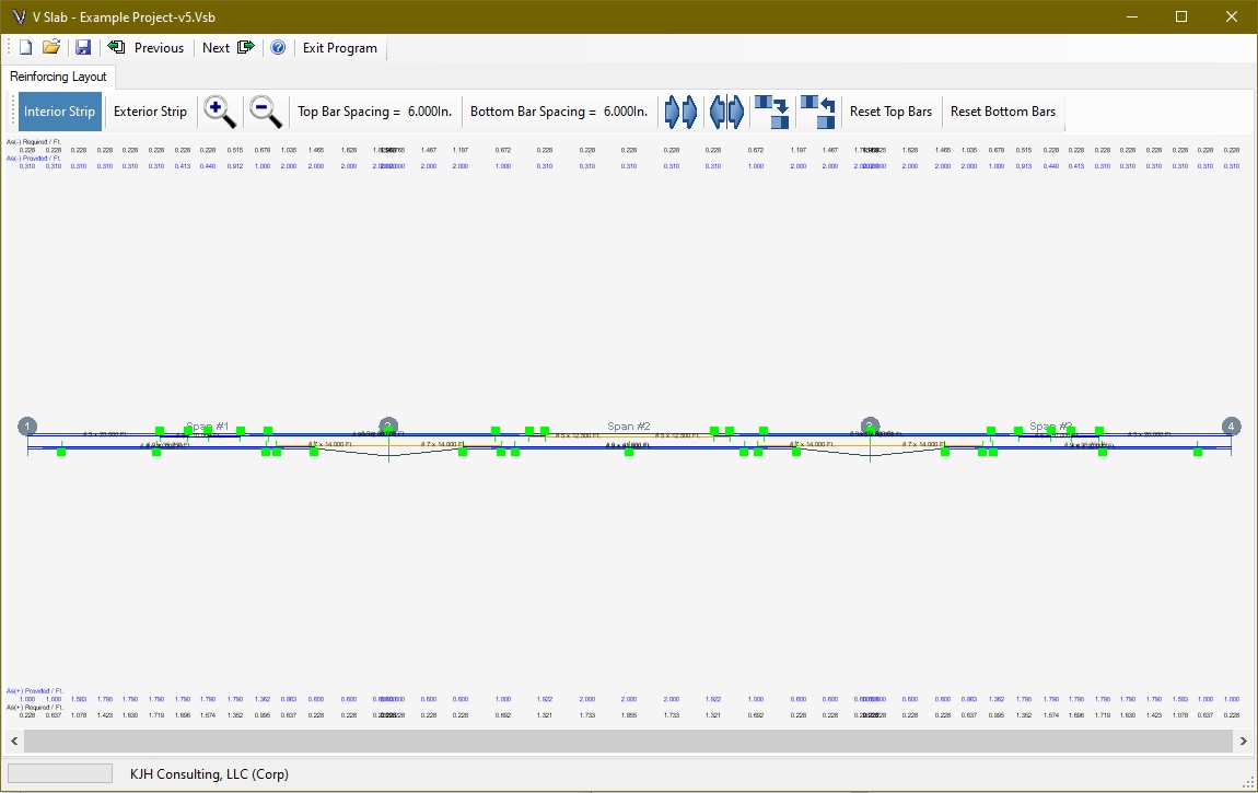
Zoom and pan to navigate to an area for editing. The mouse wheel can be used to zoom in place of the toolbar buttons. Use either the scroll bar or the left mouse button to pan left and right. After zooming to an area, move the mouse cursor over the bar you want to edit and click the left button.
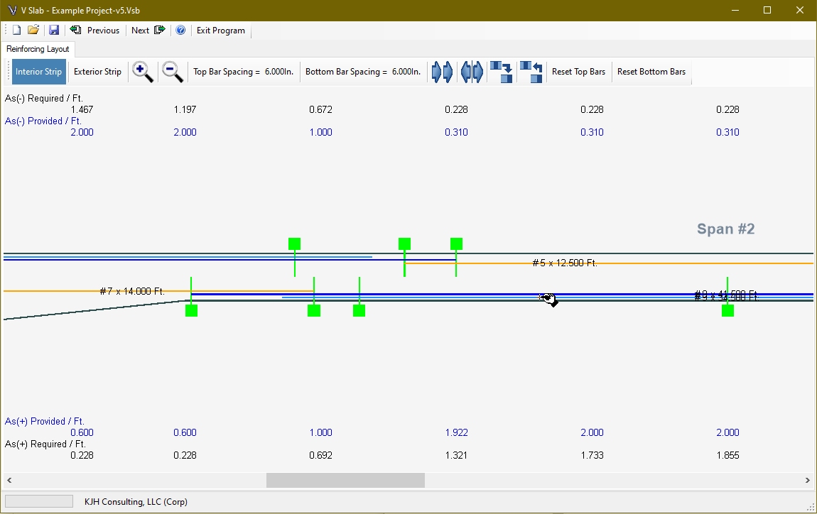
A dialog box will open for the bar selected. The light blue bar is the cut bar, and the dark blue bar is the continuous bar. The cutoff points can be changed for the cut bar.
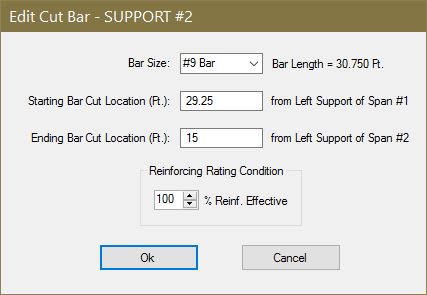
The continuous bar can be modified to add up to two splice bars right and left of the main continuous bar. The reinforcing rating condition can be modified for both the cut bar and continuous bar. Enter the percent of the bar area that remains effective for use in determining the load rating moment calculations.
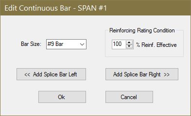
NOTE TO DESIGNER: For top bars in bridges with three or more spans, the continuous bars (main or splice) will end at mid-span from each support. This is a programming termination and is not intended to be a real world condition. The designer must detail this condition appropriately. If the same bar size is used on each side, one bar may be used to satisfy both sides. Otherwise an appropriate length splice should be detailed.
The toolbar buttons provide the following functions:
![]()
- Switch between the interior and exterior strip reinforcing steel layout screens
- Zoom in and out
- Change the top and bottom reinforcing bar spacing (between the continuous and cut bars)
- Copy bars from one support or span to another one.
- Mirror bars from one support or span to another one.
- Copy the entire layout from the interior or exterior strip to the other.
- Reset the top or bottom continuous/cut bar layout starting with the current bar spacing. (if a suitable layout cannot be obtained, the current spacing will be reduced until one can be found. This will also clear all splice bars in the layout.)
If the designer wants a different spacing than originally presented, modify the spacing and select Reset Top/Bottom Bar to have the program create a new bar layout. If the project was previously saved after a reinforcing layout was presented, the new layout will remain unless the user does one of the following: changes the number of spans, or selects the “Reset Top/Bottom Bars” button.
To determine if the reinforcing bar layout is adequate, the program creates section checks at appropriate locations for the top and bottom bars. Section check points are placed at the ends of spliced bars and at the extension points of cut bars. In addition, if the maximum area of steel occurs away from these points another section is added.
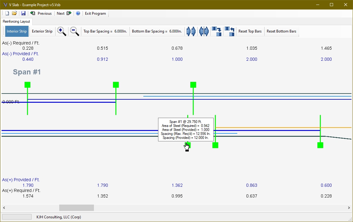
If the area of steel provided is greater than required, and if the spacing provided is less than the maximum allowed, then the section check box displayed on the layout window will be green. If these conditions are exceeded, the box will be displayed as red. To display the detailed information at the section, place the mouse cursor over the box and a textbox will appear.
DETERMINING REINFORCING STEEL AT A SECTION
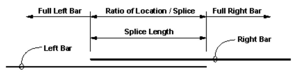
To calculate the area of steel at a section, the program reviews the location relative to the continuous bar and cut bar. For the continuous bar, the following detail describes how the program determines the useable reinforcing steel at a section:
NOTE TO DESIGNER: The program assumes adequate splice lengths are provided to develop the bar capacity. The designer is responsible for selecting the appropriate splice length. The Pass/Fail condition presented is only applicable if the proper lengths are provided in the project reinforcing development and splice table.
For the cut bar, the program calculates the development length of the bar without reduction factors. The top bars use the top bar modification factor and the development length of both bars are adjusted for epoxy coating. The bar spacing and cover conditions are used in the calculation. For the cut bar, the following detail describes how the program determines the useable reinforcing steel at a section:
The provided area of steel is the sum of the continuous and cut bar reinforcing steel. The required area of steel is determined using the effective depth calculated using the largest bar at a check section point.
LOAD RATING SECTIONS
For load rating purposes, a section is provided at each design point as well as the ends of splices and cut bar extensions. To determine the reinforcing steel provided, the effective reinforcing rating percentage is applied to the bar size before the ratio is calculated as described above. However, the development length of the cut bar is calculated assuming the full bar capacity.
Each support can be designed as either a cap type or wall type substructure. The cap type support is flexible while the wall type is considered to be rigid. This affects the way the pile loads are calculated as well as the reinforced concrete design.
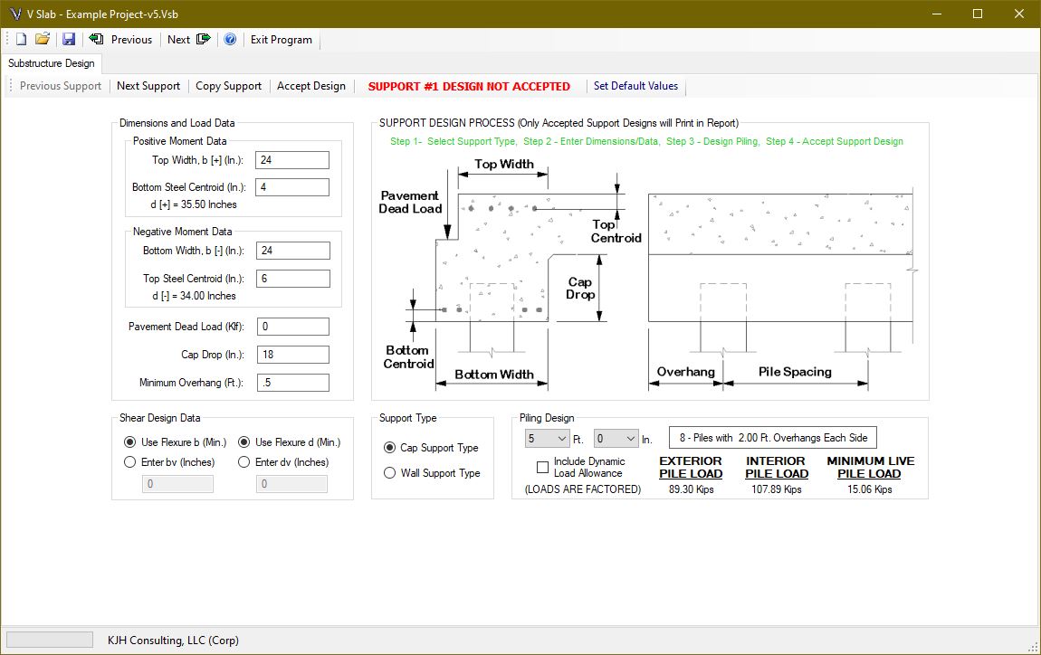
If a wall type is selected, only the cap drop (which becomes the wall depth), the bottom width, and if it is the first or last support, the pavement dead load will be enabled. The other entry fields are needed for the cap type support.
PILE DESIGN
The user selects the pile spacing in feet and inches and the program calculates the number of piles and the overhang using the minimum overhang dimension specified. Change the minimum overhang dimension if a different overhang value is preferred. All pile loads are factored. The user can specify if the piling load should include the dynamic load allowance on live loading. This option is included because the piling can be constructed integrally with the superstructure, which may require special loading consideration. The pile loads are provided for exterior, interior and for the minimum live load case. The minimum live load case is provided to ensure piling uplift is identified, if applicable. This case uses a live load factor of 1.75 with a dead load factor of 0.9.
For wall type supports, the dead load reaction is applied evenly to each pile, and the live load reaction is applied over a 10 foot width placed against the edge of the rail. If the bridge has more than one lane, additional lane reactions (acting over a 10 foot width) are placed against the previous lane. The lane contribution is applied to the exterior piles using P/A + M/S for the piles assuming a rigid group. The maximum and minimum exterior pile loads are provided.
For cap type supports, the dead load is applied to the interior piles by tributary width, and to the exterior pile by the lever rule assuming a pin at the first interior pile. The rail load assigned to the edge beam is applied as a distributed load over that width. The live load reaction is reduced by the amount of two factored wheel loads, and the remaining reaction, times the total number of lanes, is applied as a distributed load over the length of the pile cap.
Wheel loads are applied to exterior piles by the lever rule. If there are only two piles, the interior pile load is zero because there are no interior piles. With three or more piles, the interior pile load, positive moment, negative moment and shear are determined assuming a two span continuous condition (conservative). Two wheels per lane, up to a total of six wheels, are placed (6Ft. / axle and 4 Ft. between axle group) at tenth points to determine the maximum load values.
CAP DESIGN
The moments and shears determined as described in the previous section are used to calculate the required areas of steel. The section is checked to ensure it is tension controlled. Minimum steel is calculated as 1.2 times the cracking moment with the section depth equal to the slab thickness plus the cap drop. This information is presented in the report so the designer can determine the appropriate reinforcement amounts if their condition varies from these assumptions.
Shear design is based on the sectional design model and the simplified method [5.7.3 using 5.7.3.4] with Beta = 2.0 and Theta = 45 for concrete strength calculations. The calculated shear steel area is provided in square inches per foot for both stirrup legs. A sample calculation would be a #4 bar U-stirrup at 6 inches on center (Av = 2 legs x 0.2 sq. in. per leg x {12”/Ft.} / 6” = 0.8 square inches per foot). The reported shear calculations are intended to provide information to assist in developing an appropriate design. The applicable code provisions must be followed regarding minimum shear steel area and stirrup spacing.
WALL DESIGN
Depending of the dimensions and other uses of the wall, detailed design may not be required. The report presents temperature and shrinkage requirements in accordance with [5.10.6]. This minimum steel will be required regardless of any calculated area of steel requirements.
There are many other loads a wall type can be required to carry including: soil pressure, wingwalls, highway surcharge, stream flow, ice, etc. These combinations are beyond the scope of this program. The designer should review the wall condition for other loading and ensure that at least the minimum values are provided.
When the design is complete, the program output is presented in the form of a report. In demonstration mode, not all of the output will be included in the report and there are no option for printing or saving. If the software is licensed, the report will provide complete Information.
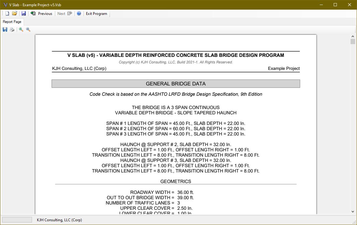
The report produces a detailed report in PDF format. This can be saved directly to a PDF file or it can be sent to any available printer. Some of the data can be suppressed using the appropriate checkboxes on the loading pages. This can significantly reduce the number of pages in the report.
V Slab Technical Verification Section
This section provides additional documentation for verifying the results of V Slab calculations and output. This includes loading analysis, design calculation methods and code checks.
Bridge structural design begins with a loading analysis to determine the dead and live load demand, based on the geometric layout selected. As such, verification of loading analysis is the first step in assessing software performance.
After verifying the live loading, the design methodology is detailed in the next study, which completes superstructure calculation checks using the same bridge geometry.