
V Slab ~ Variable Depth Slab Bridge Design Software
V Slab is a structural analysis and design software package developed for reinforced concrete flat or haunched slab bridges under the American Association of State Highway and Transportation Officials (AASHTO) LRFD Bridge Design Specification.
V Slab can also provide HL93 Inventory/Operating and special vehicle LRFR load ratings in accordance with the AASHTO Manual for Bridge Evaluation.
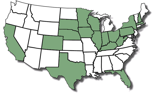
Engineering firms of all sizes have used V Slab for bridge designs. From small firms to international companies, V Slab is the choice for LRFD slab bridge designers across the country. The graphic to the left depicts states where consulting firms (Firm Headquarters Only) have purchased licenses of V Slab.
User-friendly and intuitive, V Slab is a software solution to efficiently design and optimize slab bridge details. This results in cost-effective bridge construction plans and more profitable project budgets.
V Slab was written by a practicing Bridge Engineer. The software assists the designer in efficiently reviewing options to quickly design and detail slab bridges of various types. Numerous options are available to model the majority of the conditions experienced in practice.
Design Slab Bridges ranging from a simple span or up to 9 continuous spans. Spans can range from 10 feet to 90 feet.
Variable depth slabs are deeper at the interior piers of continuous spans where higher moments occur. This creates a more efficient structural system and therefore improved economics. V Slab makes the difficulties associated with variable depth slab analysis and design easy.
Experienced designers will find V Slab intuitive. Easy to learn and easy to use, it cuts design time to minutes. Production-oriented output makes detailing simple and provides sufficient information to verify results.
Reinforcing steel requirements are calculated for strength as well as code-prescribed maximum bar spacing. The designer can also account for deterioration by reducing reinforcing steel effectiveness for load rating.
Many times the designer is required to check agency-specific vehicles. Up to 10 special vehicles, with up to 12 axles each, can be entered. A standard lane loading can be included and specific load factors can be selected to design and load rate the special vehicle.
The program guides the user through the superstructure design with a two-bar pattern. The program selects initial bar cut locations and completes code spacing checks. Bar selections are graphical and interactive, allowing the designer to adjust sizes and spacing to meet their requirements. Splice bars can be added to improve economics.
Substructure design includes wall and cap types. A pile spacing is selected and pile loads are immediately presented. Cap flexural and shear reinforcing is calculated by the program, and the user can enter customized design parameters or use calculated values.
Copyright © KJH Consulting, LLC (06/05/2026), All Rights Reserved.